Jan 6, 2013

RoboTank #3 / motor driver version 2

Here is the second version of the programmable motor driver.


It uses a L239D chip to drive two DC motors and modulate their speed individually.   The board can be controlled with only two input wires.  This is made possible through an interface program loaded in the ATMEGA238 (same as Arduino UNO) onboard chip.  The interface chip and the driver chip are running on two separate power circuits and both are in sockets and can be easily replaced or, in the case of the ATMEGA238 chip, reprogrammed.

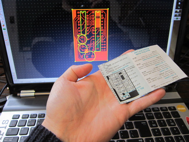
Using the ATMEGA238 chip makes this motor driver very versatile since 10 pins (5 digital and 5 analog) are still available for inputs/outputs.  This driver can then be reprogrammed and customized rapidly.  Here is the etching pattern I made using ExpressPCB:


Finally here's the part list:

  • 1x - Small copper clad laminate board
  • 1x - 16 pins socket
  • 1x - 28 pins socket
  • 2x - 0.1uf capacitor
  • 1x - 16MHz crystal
  • 2x - 6 pins female headers
  • 2x - PNP transistors
  • 2x - Inputs Screw Terminal 3.5mm (2 pins)
  • 2x - Inputs Screw Terminal 5mm (3 pins)
  • 1x - L293D (or SN754410)
  • 1x - ATMEGA238P-PU
  • Some wires
  • (optional) 1x - Heatsink for the L293D
I'll put up a Instructables ASAP with the PCB layout file.  Until then I can send it to you if you contact me directly.

Jan 4, 2013

RoboTank #2 / homemade PCB

This was my first attempt at making a PCB at home.  I follow this awesome tutorial explaining how to make PCB using a laser printer.  The first step was to design the board.  For this I used ExpressPCB free software.  Then I printed the design on a magazine paper.


The next step (which took me 3 tries) was to transfer the design to the copper plate using an iron.  This was a big learning experience about the necessary spacing between the traces and the amount of time to apply the iron.  In the end I got something that was good enough to go to the next step.


As suggested, I corrected the mistakes using a Sharpie pen.  After a Ferric Chloride bath here is the result:


I used a sponge to rub the surface during the etching.  Apparently the Sharpie fix is not meant to survive that kind of abuse.  This is still fixable.  The final step was to drill the through holes and do the assembly.


RoboTank #1 / The base

This is the first post about this new project using the TAMIYA Tracked Vehicle Kit as a base for building a robotic tank vehicle.  This will be an ongoing project and you should expect many posts about this subject.  Here's a video where I'm building one of the two kits I got:


Since the kit comes with  a single motor assembly allowing the tank to only go straight forward or backward,  I also bought the Double Gearbox from TAMIYA.  It can be assemble with 4 different ratios: 12.7:1, 38.2:1, 114.7:1 and 344.2:1.  I went for the 114.7:1 ratio since speed is not a necessity.


The tank kit is not build to fit with this particular gearbox so I had to modify the base plate to accommodate the support bar that came with the gearbox but that was meant for another kit.


I want to have an standard Arduino board running as the brain for this project.  Since there will probably be a lot components to control, I needed to drive the motors using only 2 pins from the Arduino board.  So, the next step was to build a motor driver PCB that would accept the inputs from the Arduino and take care of the rest.  This was a perfect excuse to make my first homemade PCB.  I'll get to that in the next post.


Dec 23, 2012

LEGOtiny

After my last Mini RC Car project I knew I wanted to make a smaller better one.  Some months later and this is the result:


The reason why this one is in a LEGO body is because of this question on LEGO Stack Exchange where it was asked if it was possible to power the small LEGO City wheels.  At that point I had already started playing with micro DC motors and I also started using the ATtiny chip.  This was a perfect storm.  I had to build a super small LEGO vehicle.

Here are all the parts needed to make this build:


  • Set of gears from a race track car
  • LEGO wheels set
  • LEGO brick 2x2
  • Micro motor
  • 0.1uf capacitor
  • Transistor
  • Diode
  • ATtiny
  • Socket
  • Power adaptor
I'll go over the small details in an Instructables ASAP.  For now here's shot from the inside:


Here's a video where I show the final result:


Dec 18, 2012

Jumping on board

Here his a 'how-to' for running two low voltage (3.3V) micro controllers on a breadboard.

The first one is the chip(s) used with the TI LaunchPad. I've tested this setup with the MSP430G2211 and the MSP430G2231. The chip will run at 3.3V and is rated up to 3.6V.


This setup needs a 100nf capacitor between pins 1 and 14, then pin 10 needs to be connected to positive using a 47k resistor.  I use the LaunchPad board to program the chip before transferring it to the breadboard and this is pure laziness since there must be a way to program it in place.


The second one is the ATtiny (in this case the Attiny13) which can run the same code as the Arduino (ATmega328) and can be programmed using the Arduino IDE and uploaded using the Arduino board as an ISP for ATtiny.  You will find all kind  of help online for using the ATtiny13, ATtiny45, ATtiny85, ATtiny44 or ATtiny84.


The chip will run at 3.3V or 5V.  As you can see by this diagram, this is the most simple one to use.  No crystal and no resistor are necessary for running it.