Showing posts with label electronics. Show all posts

Sep 6, 2013

Inside the box

So close I can almost touch it. Parts for the LEGO Test Machine #2 are coming and I feel like a kid before Christmas. Here's some pictures taken by the guys at The LittleBritish Robot Company while boxing all the goodies.


WhoooOOOoooo motors


Looking at the content I got inspired to create a new design focus around the use of the Makeblock wheels.


The top part (1) would go back and forth to assemble the brick by compressing them together. Disassembling the bricks would be done by a claw system (2) able to twist off the bottom brick. Finally the bottom plateau (3) would go up and down using an off-centred wheel, helping in the process of assembling or releasing the parts. It's just a rough idea but feel free to leave your thoughts and suggestions.

Now, how can I make time go faster? I could go to sleep until the package arrive. Naaaaaah I'll probably wait in front of the door like Scott Pilgrim.

Added:
You can see all the 'boxing' pictures on my G+ album

May 27, 2013

LEGO Wear Test #2 - Design


I have the basic design  for the second LEGO wear test machine.  Here is a prototype made with Castilene plastic:


The result will be a long rig that will hold all 10 pairs of LEGO bricks to be tested simultaneously.  The parts will be made of machined metal fitting the brick shape as precisely as possible.  One thing that I learned from the first test is that it takes a lot of strength to hold those bricks, which is why I'm overkilling this one.


The bottom part is composed of two halves enabling the rig to either hold tight or release the piece completely.

Following comments that many viewers/readers have left, here are the new requirements:
  • Use a rotation motion to remove the LEGO bricks.
  • Keep the test speed at 10 seconds per iteration to prevent heat from friction.
  • Test 10 sets at the same time.
  • Test bricks from different eras.
  • Once the LEGO bricks have fallen the first time, rotate them 180 degrees to continue testing until it fails again.
  • Run the machine in the shed to keep the noise down.
  • Have a way to query the test status while it's running.
Not following comments that some viewers/readers have left:
  • This will not solve global warming
  • I will keep playing with LEGO bricks
  • My accent should not improve before the next test
One thing I'm leaving out is to have many control points and this test will [again] only count the iterations.  I initially wanted to monitor forces and current but it makes no sense with this simultaneous test. Next time...

For the test I've done my best to select bricks from 3 eras.  The new ones (3 pairs) were the easiest to find while the 2 pairs from the mid 70s posed a challenge.  It started with one pair I took from a set  bought at the flea market.  It was the set #370 from the mid 70s.  Looking at those two white bricks I noticed that they had a unique casting mark on one side.  After a lot of digging, I finally found two bricks with similar marks.  In a very non-scientific moment I declared that this unique feature probably means that they're from the same era.  Shoot me.


Now that the 10 pairs of bricks have been selected they are set aside until the test and other bricks are used during the rig's development.  Also, in a wave of madness, I might even run this new test twice with the side effect that I'm slowly destroying all the 2x3 bricks in the house.


May 2, 2013

Test design & LiveTankGame


Well, while I'm working on the design of the new LEGO test rig (see test1), I'm getting back into the tank project.  My generic goal for this long term project is to design a table top robotic game that will be a cross between a live card game and robotics.  So far I will have two tank platforms to test all the robotic modules so that I can prototype the gameplay based around those features.

TA1 (aka: whydontyouworkyou...)

You may ask yourself “Where the heck are you going with this?”, and that is a good question since I don't have a final answer yet.   You see, I like building stuff and I like cool-unusual-geeky-things that I can't afford so, many times, if I want something I have a tendency to build it.  My latest crazy idea came during the last Christmas vacation when my wife and I started playing a live card game called Android Netrunner.  No it has nothing to do with mobile phones.

The box

I found this game so cool that I had this crazy idea to reinvent the same level of gameplay using robots instead of cards. Why? Well... why not? Sooooo this is going to take a long time and I have to start by testing what kind of electronic interactions/capabilities the tanks can have. Once I have enough working features I will design the basic gameplay around them and build the two game tanks. Like I said... long term and so geeky that it technically falls into the nerd realm.

Here is a short update: The mobility base is composed of a robotic tank kit and a homemade DC motor driver. The motor driver PCB still needs a bit of redesign but it's functional for now and that... is good enough. Here I am building one of the two tank kits:


For now, the tank is controlled using an Android phone via bluetooth and I'm ready to start testing the other features like the laser, IR proximity sensors, light sensors, Ultrasonic range finder, etc...


Starting now, I will also tweet the updates using the hashtag #livetankgame.  


Apr 19, 2013

LEGO all worn out

As suggested by Christopher Gaul, I took some macro(ish) pictures of the wear patterns on both the studs of the bottom LEGO brick and the inside walls and tubes of the top LEGO brick.

Clear marks are left on the sides of the studs (bottom LEGO)


The small ridges on the inside walls (top LEGO) are visibly worn down.  There is also damage to the tubes and even the walls themselves.


Here are the 2 pictures in full resolution (sorry for the low quality) without the notes:


CSI case #66531

Jan 6, 2013

RoboTank #3 / motor driver version 2

Here is the second version of the programmable motor driver.


It uses a L239D chip to drive two DC motors and modulate their speed individually.   The board can be controlled with only two input wires.  This is made possible through an interface program loaded in the ATMEGA238 (same as Arduino UNO) onboard chip.  The interface chip and the driver chip are running on two separate power circuits and both are in sockets and can be easily replaced or, in the case of the ATMEGA238 chip, reprogrammed.

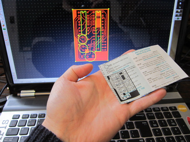
Using the ATMEGA238 chip makes this motor driver very versatile since 10 pins (5 digital and 5 analog) are still available for inputs/outputs.  This driver can then be reprogrammed and customized rapidly.  Here is the etching pattern I made using ExpressPCB:


Finally here's the part list:

  • 1x - Small copper clad laminate board
  • 1x - 16 pins socket
  • 1x - 28 pins socket
  • 2x - 0.1uf capacitor
  • 1x - 16MHz crystal
  • 2x - 6 pins female headers
  • 2x - PNP transistors
  • 2x - Inputs Screw Terminal 3.5mm (2 pins)
  • 2x - Inputs Screw Terminal 5mm (3 pins)
  • 1x - L293D (or SN754410)
  • 1x - ATMEGA238P-PU
  • Some wires
  • (optional) 1x - Heatsink for the L293D
I'll put up a Instructables ASAP with the PCB layout file.  Until then I can send it to you if you contact me directly.

Jan 4, 2013

RoboTank #2 / homemade PCB

This was my first attempt at making a PCB at home.  I follow this awesome tutorial explaining how to make PCB using a laser printer.  The first step was to design the board.  For this I used ExpressPCB free software.  Then I printed the design on a magazine paper.


The next step (which took me 3 tries) was to transfer the design to the copper plate using an iron.  This was a big learning experience about the necessary spacing between the traces and the amount of time to apply the iron.  In the end I got something that was good enough to go to the next step.


As suggested, I corrected the mistakes using a Sharpie pen.  After a Ferric Chloride bath here is the result:


I used a sponge to rub the surface during the etching.  Apparently the Sharpie fix is not meant to survive that kind of abuse.  This is still fixable.  The final step was to drill the through holes and do the assembly.


RoboTank #1 / The base

This is the first post about this new project using the TAMIYA Tracked Vehicle Kit as a base for building a robotic tank vehicle.  This will be an ongoing project and you should expect many posts about this subject.  Here's a video where I'm building one of the two kits I got:


Since the kit comes with  a single motor assembly allowing the tank to only go straight forward or backward,  I also bought the Double Gearbox from TAMIYA.  It can be assemble with 4 different ratios: 12.7:1, 38.2:1, 114.7:1 and 344.2:1.  I went for the 114.7:1 ratio since speed is not a necessity.


The tank kit is not build to fit with this particular gearbox so I had to modify the base plate to accommodate the support bar that came with the gearbox but that was meant for another kit.


I want to have an standard Arduino board running as the brain for this project.  Since there will probably be a lot components to control, I needed to drive the motors using only 2 pins from the Arduino board.  So, the next step was to build a motor driver PCB that would accept the inputs from the Arduino and take care of the rest.  This was a perfect excuse to make my first homemade PCB.  I'll get to that in the next post.


Dec 23, 2012

LEGOtiny

After my last Mini RC Car project I knew I wanted to make a smaller better one.  Some months later and this is the result:


The reason why this one is in a LEGO body is because of this question on LEGO Stack Exchange where it was asked if it was possible to power the small LEGO City wheels.  At that point I had already started playing with micro DC motors and I also started using the ATtiny chip.  This was a perfect storm.  I had to build a super small LEGO vehicle.

Here are all the parts needed to make this build:


  • Set of gears from a race track car
  • LEGO wheels set
  • LEGO brick 2x2
  • Micro motor
  • 0.1uf capacitor
  • Transistor
  • Diode
  • ATtiny
  • Socket
  • Power adaptor
I'll go over the small details in an Instructables ASAP.  For now here's shot from the inside:


Here's a video where I show the final result:


Dec 18, 2012

Jumping on board

Here his a 'how-to' for running two low voltage (3.3V) micro controllers on a breadboard.

The first one is the chip(s) used with the TI LaunchPad. I've tested this setup with the MSP430G2211 and the MSP430G2231. The chip will run at 3.3V and is rated up to 3.6V.


This setup needs a 100nf capacitor between pins 1 and 14, then pin 10 needs to be connected to positive using a 47k resistor.  I use the LaunchPad board to program the chip before transferring it to the breadboard and this is pure laziness since there must be a way to program it in place.


The second one is the ATtiny (in this case the Attiny13) which can run the same code as the Arduino (ATmega328) and can be programmed using the Arduino IDE and uploaded using the Arduino board as an ISP for ATtiny.  You will find all kind  of help online for using the ATtiny13, ATtiny45, ATtiny85, ATtiny44 or ATtiny84.


The chip will run at 3.3V or 5V.  As you can see by this diagram, this is the most simple one to use.  No crystal and no resistor are necessary for running it.


Aug 23, 2012

Control LEDs with Raspberry Pi


Using an old hard drive cable, I built a GPIO breakout cable then proceed to make an LED blink... a classic 'Hello World' of electronics.  I followed this diagram for the connections.


Plug the wires and follow these steps:
  1. Boot the Raspberry Pi
  2. Login as root (embrace your dark side)
  3. Getting ready to output in GPIO4:
  4. $ echo "4" > /sys/class/gpio/export
    $ echo "out" > /sys/class/gpio/gpio4/direction
  5. Turn GPIO4 on:
    $ echo "1" > /sys/class/gpio/gpio4/value
  6. Turn GPIO4 off:
    $ echo "0" > /sys/class/gpio/gpio4/value


Tada!

I'm now using WiringPI c++ library.  Here's a good reference to get started at Limina.Log. And a good pins reference table.

Aug 12, 2012

A new life for RCX 2.0


My LEGO Mindstorm had been unused for years now especially since I started using micro-controllers like BasicStamp and now Arduino. It had a short revival last winter when I used it to build a Star Wars R2-Unit crane for my twins. It was a real success and they played with it for two weeks straight.

Initially I was happy that my RCX was being used again but very puzzled that, after that playing stint, they had not included this new motorized brick into their regular LEGO play. Why? Maybe the cabling or specially the gears were a bit much for their age (7).

Lately my son made yet another awesome LEGO thingy and I told him he could make one part spin if he used the motors. He suddenly looked defeated and told me that “the pump thing is hard”. I finally knew why he was not using the RCX. He thought that the pneumatic system we used when making the crane, was the only way to make a working machine. Happy to enlighten him, I explained that he could use the motors alone and, at that very moment, I saw that his little brain was about to explode with ideas while he ran back to the LEGO boxes. His first creation was this 4 wheeled vehicle with one motor per wheel.


Then he dug up my old LEGO RCX 2.0 Mindstorm book that came with the kit, went through it one evening, found a line-following robot and built it the next day. I heard the perplexity in his voice when he called me saying “It's not working!”. The robot, going in circle, was missing the right code. I told him that building the physical robot was half the job and that it needed a program to tell him what to do. Of course now he wanted us to put the program in the robot.
I didn't want to disappoint him but the last time I pushed code on an RCX brick was in 2001 with a Windows XP computer. The software CD was probably lost in some storage box and, adding to the problem, loading a program must be done using a LEGO Infrared USB device (LEGO USB Tower) which are probably not supported anymore. Or so I thought.

I recovered my LEGO USB Tower and, ready for some major Internet archeology, Googled about LEGO RCX. I quickly found that Not Quite C (NQC) was still going strong. It was the programming language I used 10 years before. Not only that but I found that the LEGO USB Tower was now directly supported into Linux. So I plugged it in and BAM! /dev/usb/legousbtower0. Minutes later I uploaded a test program on the RCX brick and ran it. Victory is ours!


I coded a very simple program to show my son some basic logic in programing and now he's completely shocked by the fact that he can make a full robot, including the code.

I've created a monster and I like it.

More Geek info after the break

May 30, 2012

Mini RC Car - Part 5 (final)


After weeks of 'other things', here is the 5th and final post on the Mini RC Car project.


It's alive!!!

This final configuration works on a single 9v battery. Yes only one power supply because I found the real source of the noise problem coming from the DC motor. Like any good bug it was a code 12 since I assumed that the motor had a capacitor on it... NOT!  Here you can "see" the result.


Parts:
1x racetrack toy car
1x micro servo
1x 9v battery
1x 5v power regulator
1x pn2222 transistor
1x 1N4001 rectifier diode
4x ceramic 0.1uf capacitors
1x 16MHz crystal
1x 28 pin socket
1x 4 pins female headers
1x 3 pins male headers
1 9v snap connector
1 Atmega328
1 BlueSmirf bluetooth breakout board
1 PCB
1 Wires
scrap metal/wood for structure

Tools:
Dremel
Soldering iron
Hot glue gun
Arduino board (e.g. UNO) for programming the chip
Android device with bluetooth


For the maniacs out there I'll probably add this on Instructables where I'll go over all the geeky details.

To view the whole project go here.

Thanks for reading.

Feb 21, 2012

Mini RC Car - Part 4

Back on track with 5v...continuing the Mini RC Car build.

So I couldn't wait on my 3.3v voltage regulator.  I decided to switch the car to 5v and use a good old 9v battery.  This is what it looked like when I tested the new power system:


This has to be the ugliest RC car ever made.

After getting over the look of the beast, I now have to do the following:

  • Test the servo
  • Clean up the electronics (there is still some quick prototyping part or assembly)
  • Make a more permanent stack assembly for the battery, power regulator and circuit board.
  • Programme the Arduino and the Android phone (remote)

This shouldn't be too long.  Here's the car running a test with the new power system:


To view the whole project, go here

Feb 14, 2012

Mini RC Car - Part 3

A few bumps in the road...continuing the Mini RC Car build.


First I decided to get rid of the variable voltage regulator.  It was causing all kinds of problems mostly because I'm using a 3.7v power source.  Anyway the Arduino runs fine for now and I have some 3.3v regulators coming through mail pretty soon.

A glitch never comes alone but I'm lucky since the next problem was simple. The DC motor is creating noise feedbacks that are confusing the servo.  That one is an easy fix by adding a 0.1uf capacitor on the motor.

The third one is a show stopper. Or maybe I should say 'a show slower'.  The cellphone battery I'm using is not strong enough for this whole operation.  It's a 3.7v 850ma LiPo cell.  I have to power the Arduino, the BlueSmirf Bluetooth board, the servo and the DC motor which is done using a transistor.  I guess I should have done some calculations first.

Soooo, I'll get to that and I'll order the right battery.  Until then, PAUSE on this project.   Mmmmm, that gives me an opportunity to start another thing.  Muha ha ha ha ha

To view the whole project, go here

Feb 11, 2012

Mini RC Car - Part 2

...continuing the Mini RC Car build.

To attach the steering servo, I drilled holes in the frame and bolted the two together.


I then hot-glued the front frame to the rear half, making sure I had enough ground clearance and all 4 tires on the ground.

The next step was creating a board that would support the Arduino chip, a socket for the bluetooth breakout board, the 3.3v voltage regulator and a socket for the servo connector.  Here's the prototype:


After a bit of soldering, here what I have so far:


Now that I have all the main components, I'll do the final assembly and start programming the on-board Arduino code and the Android controller app.

To view the whole project, go here

Feb 9, 2012

Mini RC Car - Part 1

While cleaning up the basement, we came up on that old electric racetrack and finally decided to get rid of that thing.  Of course I kept all the electrical circuitry and the kids kept the cars to play with.


Since I needed another project to start to justify not working on all the important stuff, I decide to re-purpose one of those car into a mini RC car that I would control using my Android phone. Communication will be done through bluethooth which I tested earlier.

My first test was to control the motor using an ATtiny13 Micro-controller.  This chip uses the same code as Arduino but has only 8 pins.  I powered the assembly using a LiPo battery from a dead cellphone.


I started by cutting the frame in two and hot glued a micro servo on the front part.


I then used a PC card slot-cover and bended it into a frame that would join the two half.

To view the whole project, go here

Jan 29, 2012

DIY Proto board

With the Arduino board, I'm using the proto shields very often. It all sounds good with the exception that I often have many ongoing projects and only two proto shields. On top of that I would like to start using the ATtiny and not only the Atmega328 and the UNO board is not made for the ATtiny.

The solution? Make my how proto board of course!

I wanted the board to be compact but still contain a mini breadboard so I decided to used one half of a mini breadboard.


To make things convenient, I also wanted to use a ZIF socket to easily change the micro-controller chip(s). Here are all the parts before assembly:


Part list:
1: ZIF socket 28 pin (~$2.95)
2: 8 pin female header (~$0.50 2x)
2: 6 pin female header (~$0.50 2x)
1: 5 pin female header (~$0.50)
1: 4 pin female header (~$0.50)
1: 16MHz Crystal (~$0.95)
1: Mini breadboard (~$3.95)
2: Capacitor Ceramic 0.1uF (~$0.25 2x)
2: Electrolytic Capacitors - 100uF (~$0.35 2x)
1: Voltage Regulator – 5V (~$1.25)
1: 9V Snap Connector (~$1.25)
1: PCB board (~$1.25)
+ some wires for connecting the components.

Total cost: ~$16.0

Here's the final product.


I'm pretty happy with it because it's small, it doesn't need a separate proto shield, I can use it with either 1 Atmega328 or 1-2 ATtiny(s) and the ZIF socket makes things a lot easier when switching chips.

Jan 15, 2012

Arduino and Micro-SD logging

Getting started with Adafruit's Micro-SD Breakout Board in 2 minutes.

Wiring
Wiring the Breakout board is very simple.
  • Connect the 5v pin to the 5V pin on the Arduino
  • Connect the GND pin to one of the three GND pin on the Arduino
  • Connect CLK to pin 13
  • Connect DO to pin 12
  • Connect DI to pin 11
  • Connect CS to pin 10


Picture shamelessly taken from its home at adafruit.com

Programming
To use the Micro-SD you need to include the SD.h library at the top of your program.  Then add the following line of code to your setup() function:

SD.begin(10);

Now you can write something on the card:

File logFile = SD.open("log.txt",FILE_WRITE);

if(logFile){
   logFile.println(“Hello World!”);
   logFile.close();
}

Finally, while humming the MissionImpossible theme, you can power off the Arduino board, take the Micro-SD card out, put the micro-SD card in an SD card adaptor, put the SD card adaptor in your laptop and look at your new file.

Muha ha ha ha ha.

Note: I used this in my last arduino/bluetooth project.   

Arduino Bluetooth Link


In a previous Arduino project, I used the BlueSmirf Bluetooth Breakout Board to communicate with my Android phone. There was absolutely no special code on the Arduino to handle Bluetooth since, by default, the BlueSmirf is set as Slave and will accept any connection call. The phone app was doing all the work.

The next logical step was to use the BlueSmirf interface by programming the Arduino. Using a second Bluetooth board, I decided to create a link between two autonomous Arduinos. To make things interesting, I've set a couple of rules for the project. I wanted to heave the same code on both Arduinos and have the whole connection process be automatic. I also wanted the Master device to scan for other devices, retrieve the MAC address, connect and send data.  Here's the video of the final result:


My biggest issue started with the Sparkfun proto shield for Arduino. It has a built-in socket for their Bluesmirf device. Nice marketing move! This socket is hardwired to use the Arduino pins 0 and 1 for communications. It all looks good until you need to use it in the real world. Here are the pros and cons:

Pros:

  • No wiring needed to connect the Bluesmirf board.
  • No extra library needed to do serial communications.

Cons:

  • You must remove the Bluesmirf breakout board every time you need to plug the Arduino board in the computer. Why? Because of the hardwired Bluesmirf socket the Arduino board communications are mixed with the Bluesmirf interface.
  • Another consequence of the previous problem: You can't used the USB serial output to the computer to send debug info. That is really annoying when debugging your project.
  • The power is always ON for the Bluesmirf.

I'll fix this by using different pins for the Bluetooth communication using the NewSoftSerial library. I will also modify the Sparkfun Bluesmirf socket to use any communication pins and to have control on the power usage.

For more details continue reading after the break. (Warning! Geeky stuff about code and electronics)


Nov 22, 2011

Infrared on the cheap

When you make mobile robots, infrared detectors are a must. Here's a nice specimen taken in the Internet wilderness:


The problem is the cost. Starting at $13.95 US plus tax, plus shipping from Mars and the retarded Canadian border fees... in the end, it's to much. Not only that! It takes two weeks to come here. Two week! Are they using camels? I'm living in Quebec city, it's not that small, we even have asphalt and electricity.

Deep breath

Anyway for about $2.50 you can make the 'same' thing at home with these components:
  • Detector $1.95
  • Light $0.32
  • Resistor (220 ohms) ~$0.15
  • Bit of PCB board ~$0.01


Long live DIY