Mar 29, 2015

Teeny Tiny Build

Bubble display and Femtoduino

I just received a bunch of those really cool QDSP-6064 Bubble Displays and I had to build something with them right away.


I quickly tried it using the sample code and, as I was doing that, I immediately wanted to build a small device combining this display with a femtoduino and a small LiPo battery.  I ordered two Femtoduino quite some times ago but never did anything with them. I knew they would come handy one day.  Then intent of this build is to eventually make something wearable.


For the sake of making it look nicer, I picked only red wires to match the Bubble Display look.  I also took the time to keep everything as flat as possible, trying to get a compact build that could be turnded into anything.  To make the sample code work with this new build, I had to tweak the code since I was forced to connect the QDSP-6064 pins to different Arduino pins.


There nothing fancy about this build so here is the result:


Next step? I might order an Rfduino, which is smaller then the femtoduino and have WiFi built into it.  So many possibilities...

Edit:
 This post was published on:

Aug 1, 2014

HC-05 Bluetooth link with zero code

So you want to two HC-05 modules to automatically connect together, as soon as they're powered up and with zero code? Well this is your lucky day since this can be done using the AT+BIND command.

Let's do this thing!


For this, you will need:

  • 1 Arduino (I'm using UNO)
  • 2 HC-05 modules
  • 1 breadboard
  • Wires
  • Arduino IDE (I'm using version 1.0.5-r2)


Step 1 - Code and Wires

To bind the two HC-05s, we will need to input AT commands manually which can be done using this simple code made by techbitar.

1.1 Upload the code to your Arduino.
1.2 Using one of your 2 HC-05, follow very carefully the wiring instructions (this is where most people make mistakes.)
  Note that the pins layout on your HC-05 might be different so read the pin label and be sure to connect the right ones.

Step 2 – Configure the Slave

2.1 Make sure the power wire(5.0v or 3.0v) is disconnected from the HC-05
2.2 Make sure the Key wire is connected to pin 9
2.3 In the Arduino IDE, goto the Tools\Serial Monitor menu
2.4 The two following settings are correctly set (at the bottom right of the window):
2.4.1 Line ending should be set to “Both NL & CR”
2.4.2 Baud speed should be set to “9600 baud”
    Note: f you had to modify those settings, I suggest to close and re-open the Serial Monitor dialog
2.5 When the Arduino is reseted (opening the Serial Monitor dialog will force a reset) you should see the following text “Enter AT commands:” in the Serial Monitor dialog.
2.7 Connect the power wire(5.0v or 3.0v) on the HC-05.  You should see the red light slowly blinking (once every ~2 seconds)
2.8 In the Serial Monitor, type AT and press Enter (or click the Send button).  The module should return OK right away
2.9  In the Serial Monitor, type AT+ROLE=0 and press Enter.  This will set the module in Slave mode. You can verify that it worked by typing AT+ROLE? (It should return +ROLE:0)
2.10 In the Serial Monitor, type AT+BIND= and press Enter.  This will remove any existing binding. You can verify that it worked by typing AT+BIND? (It should return +BIND:0:0:0)
2.11 In the Serial Monitor, type AT+ADDR? and press Enter.  This will return the MAC address of this HC-05 module. For example: my module's address is 00:13:03:19:14:07 and the command is returning +ADDR:13:3:191407. As you can see the zeros are stripped out and the formating is a bit different but, as you will soon see, this will not be a problem.  Write down on a piece of paper this MAC address.
2.12 Disconnect the power wire from the HC-05 and remove this HC-05 from the breadboard.  It is now ready to act as the Slave module.
   Note: Don't disturb the wiring since you will use it to configure the second module.

Step 3 – Configure the Master

*Start by installing the second HC-05 on the breadboard. Exactly where the first module was plugged.

3.1 Make sure the power wire(5.0v or 3.0v) is disconnected from the HC-05
3.2 Make sure the Key wire is connected to pin 9
3.3 In the Arduino IDE, goto the Tools\Serial Monitor menu
3.4 The two following settings are correctly set (at the bottom right of the window):
3.4.1 Line ending should be set to “Both NL & CR”
3.4.2 Baud speed should be set to “9600 baud”
    Note: f you had to modify those settings, I suggest to close and re-open the Serial Monitor dialog
3.5 When the Arduino is reseted (opening the Serial Monitor dialog will force a reset) you should see the following text “Enter AT commands:” in the Serial Monitor dialog.
3.7 Connect the power wire(5.0v or 3.0v) on the HC-05.  You should see the red light slowly blinking (once every ~2 seconds)
3.8 In the Serial Monitor, type AT and press Enter (or click the Send button).  The module should return OK right away.
3.9  In the Serial Monitor, type AT+ROLE=1 and press Enter.  This will set the module in Master mode. You can verify that it worked by typing AT+ROLE? (It should return +ROLE:1)
3.10 In the Serial Monitor, type AT+BIND=13,3,191407 and press Enter (of course here you should be using your MAC address that you have noted on step 2.12).  This will force the Master module to automatically link (bind) to the Slave. You can verify that it worked by typing AT+BIND? (It should return +BIND:13:3:191407)
3.11 Disconnect the power wire from the HC-05 and remove this HC-05 from the breadboard.  It is now ready to act as the Master module.

Done.

Now if you power both modules, they will connect right away. It doesn't matter if you power one before the other one.  They will always initiate the connection automatically.  All you need to use them in your next Arduino project is to open a Serial port and communicate through it.

Edit 1: Get more info on HC-05 through this previous post and this video.

This post is featured on:

May 10, 2014

A Maker in the Quebec Fortress

A couple of weeks ago I saw a tweet from @hackaday about their new hacker contest.  The prize is only a trip to space... an actual trip to space worth around 200k.  That evening I was browsing the contest page to get more details and then I reached the eligibility section where it stipulates that the following can't participate: [...]Quebec, Italy, Cuba, Iran, Myanmar (formerly Burma), North Korea, Sudan, Syria, or any jurisdiction where the Contest would be restricted or prohibited by law [...]


The thing is, I was not too surprised since this happens often in Quebec where we have some retarded laws to control the lotteries.  Quebec is surely not the only place in the world where lottery & gambling is controlled but I think we're the only ones that are dumb enough to think that we can control all the world-wide lotteries. The result is that Loto Quebec, the government body controlling this, is trying to impose those crazy conditions on out-of-Quebec contests. So any contest with a prize must submit to those conditions and guess what, for only a small pool of 6 million people, they don't.  You ear that, contest organizers from around the world? Keep your free money and space trips. We have maple syrup.

...

So I can't register my project on Hackaday. Life goes on.


I recently acquired an Ultimaker 3D Printer and that was a huge moment for me.  I have so many projects that can benefit from this that I don't know where to start.  After a few days of learning the limits of the printer I was ready to start working on a project, and to make it even better why not a contest. So I returned to an old ongoing Intel contest page: the Make it Wearable Video Contest.  This place is a really cool mix of art, technology and people that I want to connect with.  Well you know the twist of that story.  This project [...] is open only to legal residents of Argentina, Canada (excluding the Province of Quebec), [...].

GnhaaaaaAAAAAAAaaa.


So I was ranting to people at work about the stupidity of this law but, deep inside, I thought that it wasn't too bad for now and that I could still connect with the Maker community through blogs, videos, twitter and so on.  “I'm a good sheep, I am.” (in the voice of My Fair Lady)

Then, a couple of days ago, the proverbial sh*t hit the fan.

My 9yo son who plays with LEGO Mindstorms found out about the MoonBots contest, a Google Lunar XPrize LEGO Mindstorms Challenge.  This an awesome international on-line competition for kids (9 to 17) where you have to simulate a moon mission.  Needless to say that we were bouncing ideas around and, as the vision of the project took shape, a shiver ran up my back.  I went to my computer and checked the small prints...  guess who can't compete? [...] Cuba, Iran, North Korea, Myanmar/Burma, Zimbabwe, Sudan, Syria, Argentina, Quebec, any other U.S. sanctioned country [...]


$^%&#@#$#&^ You're messing with my kids now.  The gloves are off and Nova Scotia looks like a great place to live.  Maybe I'll shop around for houses.

Where is the best place on earth for a family of Geeks and Maker?

Mar 18, 2014

Stealth Evolution

I thought I was following the evolution of the stealth technologies but I had to tweak my understanding based on recent events.


LEGO Test machine #2 is dead after 1 test

Well, that didn't last long.

The machine did 1 full test and then died at about 1/3 of the second test.  The first test result is 32,066 iterations, supporting the result from the Test Machine #1 which ended with 37,112 iterations. So the average is at 34,589 for the moment.

So, why is the machine #2 dead? It didn't died as much as it was slaying DC motors and it all came down to a bad design. One of my goal was to build the machine with only (as much as possible) the Makeblock parts that TLBRC* sent me.  It turns out that I found my nemesis in the motors that where included in the two kits. DC motors.

For something like this build, every molecules in my body was screaming stepper-motors or, at least, servos.  But NoooooOOOoooo, it had to be DC motors, so I looked around for ideas to use them in the same way I would use stepper-motors.   The result was to build physical barriers to stop the motor in known positions.  I knew this would not be good on the motor's gears so I monitored the current going into the DC motors and “tried” to stop them before they were straining. At this point in the story, all the engineers are rolling on the floor laughing. Well, 3 dead motors later, I've learned my lesson: Engineers are cruel and, most importantly, DC motors and made to run freely like wild mustangs in prairies.

The following video was made after the machine killed its first motor.  At that point I thought I could fix it:

Here is my sad video when I decided to stop the machine for good:

What now?  Thanks to Galaxy Quest, my motto is “Never give up, never surrender” and so I have 2 plans:

  1. Build a simple machine using stepper-motors.
  2. Find a DC motor friendly design and try that too.

But, in order to keep my sanity, I will take a short break from this and work on other projects.


R.I.P. LEGO Test Machine #2.  At least you did 1 full test.


*Again a big thanks to The Little British Robot Company for the 2 Makeblock kits that were used for building this project.  I will reuse those parts on a project pretty soon

Edit:
This story was covered on:


Jan 7, 2014

HC-05 Bluetooth link of 2 Arduino

In my first Arduino bluetooth experiment, I made an automatic connection between 2 Arduino using BlueSmirf modules. Based on the popularity of that post, it seems that many people are trying to do the same.

On the down side, many of the visitors are looking for a solution using the HC-05 (or other HC-XX type) modules with an AT command interface. I planned to eventually use this type of device but never got around to doing it for every bad reason imaginable including procrastination. This delay was clearly unacceptable for Lyman (one of my readers) who decided to send me 2 extra modules he could spare.

On a side note, this kind soul only has 2 followers on Twitter. Please help me fix this grievous situation.

After playing a bit with my new toy, here's what I've got:


In this first simple example, the code sets the module to be either Master or Slave, connects to one hard-coded address and starts the communication loop. While connected, the Master sends 1s and 0s to the slave who is using this 'command' to switch an LED on or off.

You can get the code on this Git repo.

Breadboard diagram (without the reset connection)

The biggest problem was to figure out how to reset the module programmatically. The [not so good] documentation explains how this can be done by cycling the power but the bluetooth chip has a reset pin that is supposed to do the same trick. I have the code to use the reset pin which I got from this blog post and I will test it soon.

On the HC-05 modules I received, the reset pin is not connected which 'forced' me into making a little hack that can barely be noticed...


The next step will be to recreate the same query and auto-connect loop that I did with the BlueSmirf. It should be straight forward since I've already tested all the necessary AT commands successfully.

Edit 1: Get some tips about using HC-05 in this video I made
Edit 2: I have a new post describing the automatic bind of 2 HC-05 module without having to write code.

Dec 31, 2013

Profiling DC motors

For the second design of the LEGO test machine #2, I stopped using rotary encoders an switched to ACS712 lowcurrent sensors.


I initially hooked them to a multimeter and an Arduino to tweak the 2 potentiometers of the sensors. Following some of the steps from this MobileAPES post, I've set the voltage (Vref potentiometer) to 2.5v without any problems but the gain (GAIN potentiometer) was initially tricky. Back when I was using the rotary encoders, I was running the motors as slow as possible (speed of 65-85) in order to not stress the parts. At those speed the current fluctuations are too large and I had to find out what is the optimal low speed of the motors.
I decided to log the data out to better see what was going on. The initial test was to log the current sensor values every 1ms while raising the motor speed from 64 to 210 by increment of 5 every 20ms. 


Yellow=speed / Blue=running freely / Red=stalled (prevented from turning)

Clearly the values I get from the motor is erratic when the speed is below ~110. So I profiled the motor again from 130 to 230.


Yellow=speed / Blue=running freely / Red=stalled (prevented from turning)

Now I know the how slow the motors can go and how to detect a stall using the current sensor. This also told me how long the motor takes to ramp up to speed when initially set at a speed of 130.

Here's the diagram of the machine made with Fritzing:


I don't have the Adafruit motor shield [fritzing] part so I used the Arduino motor shield rev3 instead. The missing details are the following: The servo is connected on SER0 (pin 9), the push-down motor is connected on M2 and the lift-arm motor is connected to M3.

The code and the Fritzing diagram for this new version are available on git.

Oct 23, 2013

Once more into the [legotest] breach

Here's a video update about the progress of the LEGOtest machine #2 (#legotest)


Here is some extra info and progress starting with something I forgot to mention in the video: the shorter lever beam.


The lever was too long and, out of sheer luck, one of the shorter beams was the exact length needed. After that, I finally strengthened the base by removing the last LEGO legs and installing the Makeblock leg I showed in the video.


Once that was done it just made sense to attach the Arduino to the front leg as you can see in this picture of the whole machine:

The Makeblock parts are provided by The Little British Robot Company

As for the double action on the new motor; it both assembles the LEGO bricks and helps disassemble them.


The two movements are difficult to perform with a single motor since assembling needs a lot of strength while disassembling is all about subtlety. The part was first designed using LEGO Technics and it took 2-3 iterations before I found a way to achieve the two movements. To better understand the motion, check out the video.


Sep 15, 2013

Unboxing and Doodle cool

The parts for LEGO Test Machine #2 have made it safely across the Atlantic.


Makeblock parts from The Little British Robot Company

You can see me open the boxes and give some initial thoughts and ideas in this video:


When opening the shipping box, I've discovered a DoodleBot which the guys from TLBRC added as a gift. It's robot that can hold a pen and use it to either draw or write. I couldn’t resist so I built it right away and tested it by trying to make it write “Thanks TLBRC”. It 'kind of' looked good on the first try but clearly there is something wrong with one of the servos or sensor. I'm pretty sure that I didn't mount the rotation sensors properly so I'll have a look at it.

Seriously, look at this little thing. How can I stay made at it?

Still it's a really cool little robot base. The Arduino board that comes with the kit contains a ton of features and most are not used by the Doodle Bot. It even has a header to plug a Bluetooth device. Needless to say that I'll most likely reuse it for a future project.

If you ever get your hand on this kit, here are a couple of tips to make it work with the current Arduino IDE. By following the kit instructions you'll get to the right drivers and select the proper board. But to open and build the code in the IDE, you can do this:
  1. Open the Doodle_Bot_Text_Demo.pde with the Arduino IDE.
  2. Click OK when prompt about creating a ''Doodle_Bot_Test_Demo” folder.\
  3. (In a file explorer) Manually copy all the other demo files into this new folder
  4. (In Arduino IDE) Manually 'Add' all those files into the project
  5. In the Alphabet and Doodle_Bot_Text_Demo files, rename all the letters functions by adding the prefix 'l'. (e.g. F() becomes lF())

That's it, you should be ready to build and upload the code to the DoodleBot.

If you have any questions let me know.

Sep 6, 2013

Inside the box

So close I can almost touch it. Parts for the LEGO Test Machine #2 are coming and I feel like a kid before Christmas. Here's some pictures taken by the guys at The LittleBritish Robot Company while boxing all the goodies.


WhoooOOOoooo motors


Looking at the content I got inspired to create a new design focus around the use of the Makeblock wheels.


The top part (1) would go back and forth to assemble the brick by compressing them together. Disassembling the bricks would be done by a claw system (2) able to twist off the bottom brick. Finally the bottom plateau (3) would go up and down using an off-centred wheel, helping in the process of assembling or releasing the parts. It's just a rough idea but feel free to leave your thoughts and suggestions.

Now, how can I make time go faster? I could go to sleep until the package arrive. Naaaaaah I'll probably wait in front of the door like Scott Pilgrim.

Added:
You can see all the 'boxing' pictures on my G+ album

Aug 28, 2013

When in doubt... TLBRC

Oh yeah, this project is rolling again, thanks to The Little British Robot Company (TLBRC).

Like many modern relationships, we met on Twitter. They followed me, I followed them. I complimented their product, they answered (knowledge of social media is a good sign). Finally, I proposed a partnership and they said yes. WooooOOOOooooo!!!!!


[pause to reflect on how cool the Internet era is and how lucky I am to be part of it]

Anyway, I will redesign the second set of LEGO testing machines using almost only Makeblock parts (distributed by TLBRC) and TLBRC parts.

To get better results than the first LEGO Test Machine, certain features and constraints will be added to this new project:
  • Gather more than one control point (e.g. adding voltage, pressure, time, ...)
  • Use a rotation motion to remove the LEGO bricks.
  • Keep the test speed at 10 seconds per iteration to prevent heat from friction.
  • Perform many tests. Hopefully, many tests at the same time.
  • Test bricks from different eras.
  • Once the LEGO bricks have fallen the first time, rotate them 180 degrees to continue testing until they fail again.
  • Have a way to query the test status while it's running.
Also, instead of machining everything myself, I will be using the following:
  • Makeblock
  • TLBRC parts
  • LEGO parts
  • Arduino and other electronic components
  • TLBRC custom milled parts (If needed)


Let's get this show on the road...

Jul 9, 2013

Endor Observation Post

The story of a kids playhouse


Some years ago, after the pool was wrecked by the weight of a record snow year, we dismantled a part of the deck. Suffering from the common makers sickness that prevents you from throwing away good material, I stored all that wood away. Here's the pile after we got it back out and inventoried what we had to work with:


The only new wood was the 4 columns and the cross braces at the base. To ensure (completely overkill) stability I went for a design where all the columns are leaning inward.


For extra QA and on the spot design-validation, my dad was part of the build. By working with him him when I was a kid, I learned to build and to problem solve. I always loved building things with him.


Here is the playhouse partway during construction:


Since we finished the playhouse some days ago, the kids have played in it every day. Like a moths to a flame all the kids in the street were also sucked into the playhouse. It is one happy place.


Now let's renovate our old bathroom...

May 27, 2013

LEGO Wear Test #2 - Design


I have the basic design  for the second LEGO wear test machine.  Here is a prototype made with Castilene plastic:


The result will be a long rig that will hold all 10 pairs of LEGO bricks to be tested simultaneously.  The parts will be made of machined metal fitting the brick shape as precisely as possible.  One thing that I learned from the first test is that it takes a lot of strength to hold those bricks, which is why I'm overkilling this one.


The bottom part is composed of two halves enabling the rig to either hold tight or release the piece completely.

Following comments that many viewers/readers have left, here are the new requirements:
  • Use a rotation motion to remove the LEGO bricks.
  • Keep the test speed at 10 seconds per iteration to prevent heat from friction.
  • Test 10 sets at the same time.
  • Test bricks from different eras.
  • Once the LEGO bricks have fallen the first time, rotate them 180 degrees to continue testing until it fails again.
  • Run the machine in the shed to keep the noise down.
  • Have a way to query the test status while it's running.
Not following comments that some viewers/readers have left:
  • This will not solve global warming
  • I will keep playing with LEGO bricks
  • My accent should not improve before the next test
One thing I'm leaving out is to have many control points and this test will [again] only count the iterations.  I initially wanted to monitor forces and current but it makes no sense with this simultaneous test. Next time...

For the test I've done my best to select bricks from 3 eras.  The new ones (3 pairs) were the easiest to find while the 2 pairs from the mid 70s posed a challenge.  It started with one pair I took from a set  bought at the flea market.  It was the set #370 from the mid 70s.  Looking at those two white bricks I noticed that they had a unique casting mark on one side.  After a lot of digging, I finally found two bricks with similar marks.  In a very non-scientific moment I declared that this unique feature probably means that they're from the same era.  Shoot me.


Now that the 10 pairs of bricks have been selected they are set aside until the test and other bricks are used during the rig's development.  Also, in a wave of madness, I might even run this new test twice with the side effect that I'm slowly destroying all the 2x3 bricks in the house.


May 2, 2013

Test design & LiveTankGame


Well, while I'm working on the design of the new LEGO test rig (see test1), I'm getting back into the tank project.  My generic goal for this long term project is to design a table top robotic game that will be a cross between a live card game and robotics.  So far I will have two tank platforms to test all the robotic modules so that I can prototype the gameplay based around those features.

TA1 (aka: whydontyouworkyou...)

You may ask yourself “Where the heck are you going with this?”, and that is a good question since I don't have a final answer yet.   You see, I like building stuff and I like cool-unusual-geeky-things that I can't afford so, many times, if I want something I have a tendency to build it.  My latest crazy idea came during the last Christmas vacation when my wife and I started playing a live card game called Android Netrunner.  No it has nothing to do with mobile phones.

The box

I found this game so cool that I had this crazy idea to reinvent the same level of gameplay using robots instead of cards. Why? Well... why not? Sooooo this is going to take a long time and I have to start by testing what kind of electronic interactions/capabilities the tanks can have. Once I have enough working features I will design the basic gameplay around them and build the two game tanks. Like I said... long term and so geeky that it technically falls into the nerd realm.

Here is a short update: The mobility base is composed of a robotic tank kit and a homemade DC motor driver. The motor driver PCB still needs a bit of redesign but it's functional for now and that... is good enough. Here I am building one of the two tank kits:


For now, the tank is controlled using an Android phone via bluetooth and I'm ready to start testing the other features like the laser, IR proximity sensors, light sensors, Ultrasonic range finder, etc...


Starting now, I will also tweet the updates using the hashtag #livetankgame.  


Apr 23, 2013

3 Great Rockets Moments

Watching the SpaceX March 7th (2013) Grasshopper test, I realized that this was one of the best rocket video moments I had seen.  Now, the minimum I could do was to list my [new] top 3.  This list is not chosen based on the historical importance of the event but on the emotional impact of seeing a rocketry  rare and amazing moment.


1
Apollo 11 landing sequence
This one may sound like an easy choice but, having read so much about the Apollo program and understanding the level of complexity of the events leading to a moon landing, this video makes me sit at the edge of my seat every time.  Especially with the added stress of the 1201-02 alarm that almost forced them to abort the landing. (info about the 1201 alarm)


Space Shuttle SRB Flight
This is a long one to watch but it's worth it. The camera is attached to the top of one of the Space Shuttle Solid Rocket Boosters (SRB).  The strange feeling of seeing the ground 'fall' away at this ridiculous speed is hard to beat.  After the noisy first part of the takeoff, there is a change in the sound while the rocket leaves the dense atmosphere followed by the silence after the separation.  But the most awesome part is when the booster enters back into the dense air with the eerie moaning-sound of the empty cylinder growing into a full roar while the rocket is slowing down to terminal velocity.


3
SpaceX Grasshopper test
This video just climbed into my top three list for the simple reason that it is filmed from the air.  This was done probably by using a sort of radio controlled camera platform (e.g. Quad-copter).  It is a strange feeling, to virtually be there and float next to this monster while it just stands in mid-air.  You expect a rocket to either do nothing on the pad or go full throttle but to see this delicate precision, now that is crazy cool.  SpaceX made it look like they do this every day... but wait.. they ARE doing this every day.  Go SpaceX!


Apr 19, 2013

LEGO all worn out

As suggested by Christopher Gaul, I took some macro(ish) pictures of the wear patterns on both the studs of the bottom LEGO brick and the inside walls and tubes of the top LEGO brick.

Clear marks are left on the sides of the studs (bottom LEGO)


The small ridges on the inside walls (top LEGO) are visibly worn down.  There is also damage to the tubes and even the walls themselves.


Here are the 2 pictures in full resolution (sorry for the low quality) without the notes:


CSI case #66531

Mar 2, 2013

Adventure Time Sword


My son was invited to the birthday party of one of his friend.  His friend mentioned to him that he liked   the Adventure Time cartoon and would like to have the sword.  My son then told him that we could probably make it because we are always building stuff.


We looked it up on the web and since it's a simple shape I decided to give it a shot.  Using the hard wood from an old shelf we took down, I drew the rough dimensions on it


I then cut the rough shape using a skill saw and a jig saw


The guard was build with 2 pieces with grooves screwed and glued on both sides


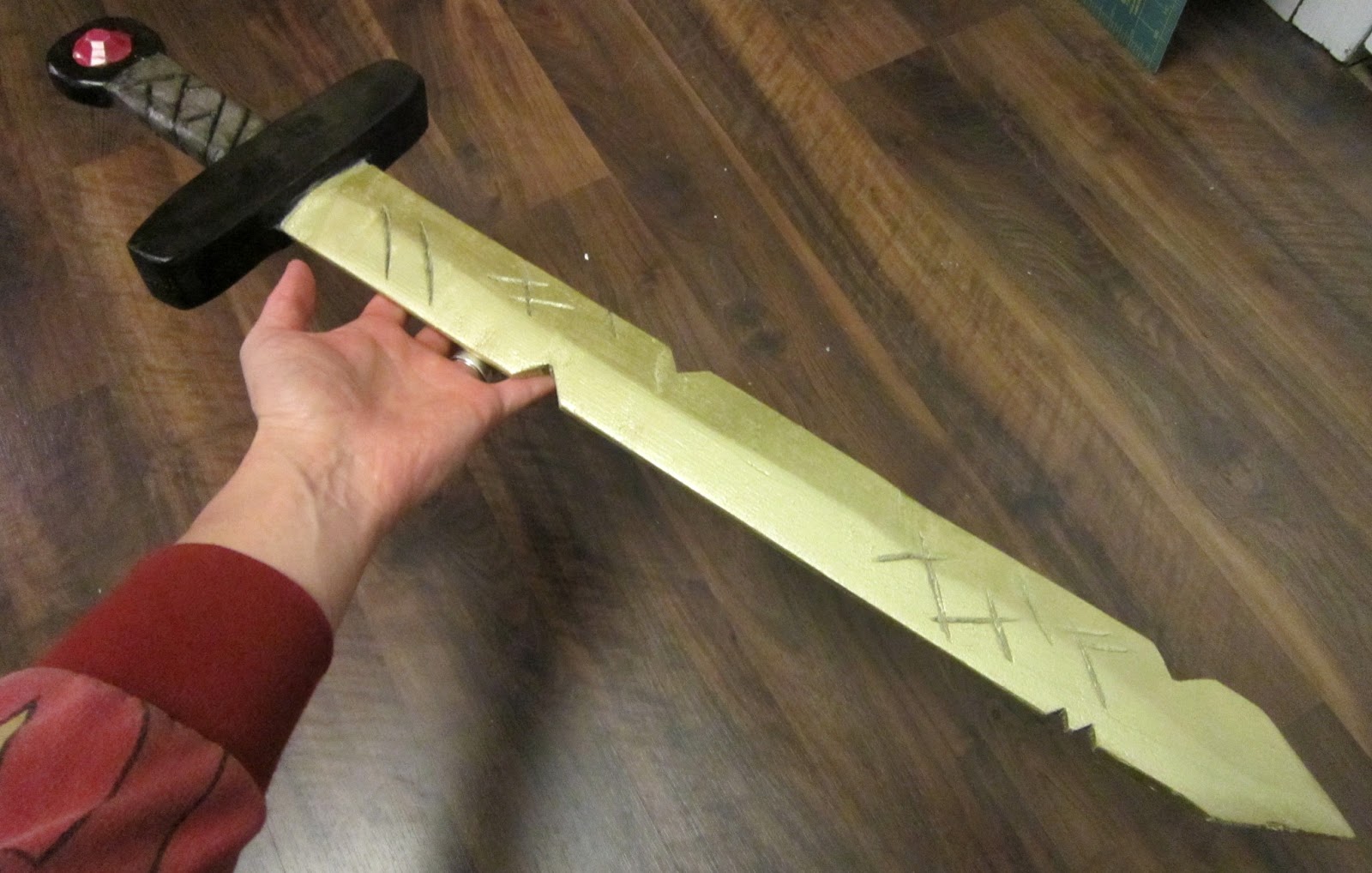
This was the fun part where I sculpted all the notches and scratches followed by some sanding


It was then time for primer and painting.  The handle was done by hand using acrylic paint


This the final product after gold metallic paint and a clear acrylic coat.  The jewel was made with Super Sculpey and also painted using acrylic paint.


Action shot with my son